1. Introduction
n perspective of rapid increase in the number of subscribers of the existing cellular networks (WCDMA/CDMA 2000, HSPA + aided 3G through LTE-Advanced4G), it is being observed that nearly 50% of the traffic is based on video signal transmission. The commercially deployed 3.9G LTE and 4G LTE-Advanced wireless networks are trying to meet up explosive demand for high quality video through sharing with social media such as YouTube and ultra HD (UHD) and 3D video from mobile devices (e.g., android tablets, smart-phones etc.) [1]. In consideration of exponential growing demand on data rates of our existing wireless networks, we are giving emphasis on the designing and implementation of WWWW(Wireless World Wide Web) supportable 5G technology implemented future generation/5G cellular system. The 5G system has not yet been standardized. The 5G mobile communications system is targeted at higher spectrum efficiency. Mobile Internet and IoT (Internet of Things) are the two main market drivers for 5G.There will be a massive number of use cases for Mobile Internet and IoT, such as augmented reality, virtual reality, remote computing, eHealth services, automotive driving and so on. All these use cases can be grouped into three usage scenarios, i.e., eMBB (Enhanced mobile broadband), mMTC (Massive machine type communications) and URLLC (Ultra-reliable and low latency communications) [2] In future 5G wireless networks., various modulation schemes such as Filterbank Multicarrier(FBMC), Generalized Frequency Division Multiplexing, Bi-orthogonal Frequency Division Multiplexing(BFDM, a generalization of the classical CP-OFDM scheme capable of providing lower intercarrier interference (ICI) and lower ISI)., Universal Filtered Multicarrier (UFMC), Time-frequency Packing(TFP) are being considered for adoption. In FBMC, the transmission bandwidth can be exploited at full capacity using OQAM(Offset-QAM) [3] The Offset-QAM-based filter bank multicarrier (FBMC-OQAM) can be considered as a promising alternative to cyclic prefixorthogonal frequency division multiplexing (CP-OFDM) for the future generation of wireless communication systems. The FBMC-OQAM provides more robustness to channel dispersion with respect to conventional CP-OFDM. The FBMC-OQAM does not require the use of acyclic prefix (CP) causing an increase in its spectral efficiency [4] II.
2. Review of Related Works
A significant amount of research is being carried out in different academic institutions and industries on identification of key benefits of FBMC as 5G compatible radio interface technology and its effective implementation. In this paper, a brief idea on the works of few researchers is outlined In 2012, et. al at [5] reviewed and emphasized the key benefits of filter bank multicarrier (FBMC) technology and provided a comparative study of different FBMC prototype filter designs under practical channel environments. In 2014, Schellmannet.almadereviewing work on the waveform design of 4G (based on OFDM) and motivated the need for a redesign for 5G in consideration of rendering unfeasibility of OFDM with the advent of the Internet of Things (IoT) and moving to user-centric processing. The authors designed a new waveform called Universal Filtered Multi-Carrier (UFMC) collecting the advantages FBMC [6]. In 2015 at [7], Taheriet. alargued that channel estimation in FBMC was not a straightforward scheme as used in OFDM systems especially under multiple antenna scenarios. The authors proposed a channel estimation method which employed intrinsic interference pre-cancellation at the transmitter side. The outcome of their work showed that their method needed less pilot overhead as compared to the popular intrinsic approximation methods (IAM) in terms of better BER and MSE performance. At [8] in 2015, Bazziet. al mentioned that Vehicle-to-vehicle (V2V) communications was anticipated as one of key future services imposing challenging requirements on the air interface such as supporting high mobility and asynchronous multiple access. The authors discussed on the design and performance tradeoffs of two 5G targeted waveforms (filter bank multi-carrier with offset quadrature amplitude modulation (FBMC/OQAM) and filtered OFDM (FOFDM) with focusing specifically on V2V communications by utilizing a realistic geometry-based stochastic V2V channel model. They showed that FBMC/OQAM outperformed F-OFDM approaches in some severe V2V scenarios. In 2016 at [9], Weitkemperet.alconducted real hardware experiments to investigate the performance of three waveform families: CP-OFDM, filter bank multicarrier with offset quadrature amplitude modulation (FBMC/OQAM) and universal-filtered OFDM (UF-OFDM). FBMC/OQAM. The outcome of their experimental work ratified that the FBMC/OQAM had the benefit of very low side lobes leading to less inter-carrier interference in asynchronous and high mobility scenarios. At[10] in 2016, Gorganiet. al proposed a high-performance and flexible Peak-to-Average Power Ratio(PAPR) reduction algorithm for FBMC-OQAM signal model and showed that their proposed algorithm had no degradation as compared to OFDM. In 2017 at [11], Lizeagaet.alfocused on the lacking of robustness of the existing IEEE 802.11, IEEE 802.15.1 or IEEE 802.15.4 standard based industrial wireless communications in perspective of real-time requirements for factory automation. The authors analyzed FBMC-OQAM, GFDM-OQAM and WCP-COQAM modulation candidates for 5G in terms of bit error rate, power spectral density and spectral efficiency over highly dispersive channels and assessed the suitability of these modulation systems for industrial wireless communications based on cognitive radio.
Additionally, they provided additional details on windowing that affecting the protection against highly dispersive multipath channels and the spectral efficiency in WCP-COQAM. In 2017 at [12], Wang et. al, demonstrated experimentally a digital mobile fronthaul (MFH) architecture using delta-sigma modulation both one-bit and two-bit) as the new digitization interface for transmission of digital signals over on-off keying (OOK) or 4-level pulse-amplitude-modulation (PAM4) optical intensity modulation-direct detection (IM-DD) links. The authors demanded that delta-sigma modulators were supportable of high-order modulations (256QAM/ 1024QAM) and such modulators were 5G compatible with filter-bank-multicarrier (FBMC) signals.
3. III. Signal Processing and Detection Techniques
In this section, various signal processing and signal detection techniques have been outlined briefly.
4. a) Massive MIMO Fading Channel Estimation
In
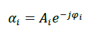
? = * = u L l l u BS l u MS l u u r t mmwave a a L N N H 1 , , , ) ( ) ( ? ? ? ? (1)where, l , u ? is the complex gain of the lth path including the path loss, ? is the path loss between base station (BS) and mobile station (MS). The variable
where, ?is indicative of Hadamard product, S is the 16×256 sized matrix whose each element is inverse of magnitude of each complex element of mmwave H
. The squared value of the Frobenius norm of the normalized channel matrix H ?is given by [13, 14]
r t 2 F N N ] H [ =(5)Digital precoding is generally used to control both the phases and amplitudes of the original signals to cancel interferences in advance. In consideration of designing digital precoding for single-user mmWave massive MIMO system, it is assumed that the base station (BS) employs N t antennas to simultaneously transmit N r data streams to a user with N r antennas (N r <N t ). The BS applies an N t × N r digital precoder D and the transmitted signal prior to D/A conversion can be presented by-
x=Ds (6)where, s is the N r × 1 original signal vector before precoding with normalized power as E (ss H )=(1/N r )I Nr , To meet up the total transmit power, D satisfies
r T F N DD trace D = = ) ( 2(7)In terms of geometrical channel presented in Equation ( 4), the digital precoder is given by [15]
F FF tr N D H r ) ( = (8)where, F=
5. H H ? c) Lattice Reduction(LR) based Zero-forcing(ZF)
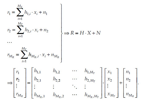
Detection In our16×256 simulated system, the received signal in terms of transmitted signal, fading channel H and white Gaussian noise n with a variance ? n 2 can be written as:
Y= = Ds H ?Hs +n (9)where, H= D H ? is the 16×16 sized equivalent channel matrix. In LR based ZF signal detection scheme, the equivalent channel matrix H is considered to be consisted of 16×16 sized lattice reduced orthogonal matrix G and a 16×16 sized unimodular matrix Usuch that H=GU (10)
The unimodular matrix U is estimated using the following relation: U= T H H (11) where, the matrix H is the Moore-Penrose pseudoinverse of matrix H and (.) T is indicative of Hermitian transpose in all cases as presented in this paper. The equation (10) can be rewritten as:
U T G=H T(12)From equation (12), the orthogonal matrix G can be estimated as:
G=(U T ) -1 H T (13)The LR-based ZF signal detection linear filter, W H can be written in terms of orthogonal matrix Gas:
T T T G G G W 1 ) ( ? =(14)Equation( 9) can be rewritten as Y=GUs +n= Gc +n (15) where, c=Us , Multiplying equation ( 15) by G T G T Y=G T Gc+ G T n (16) Neglecting noise contribution to expected signal from equation ( 16), we can write:
Y W Y G ) G G ( c ~T T 1 T = = ? (17)6. Global Journal of Computer Science and Technology
Volume XVIII Issue I Version I The estimated transmitted signal can be written as:
Y W U c ? s ~T 1 1 ? ? = = (18)7. d) Lattice Reduction(LR) based ZF-SIC Detection
In LR based Zero-forcing Successive interference cancellation (ZF-SIC) signal detection scheme, the lattice reduced orthogonal matrix G is QR factorized as: G=QR (19) where, Q is the 16×16 sized unitary and R is the 16×16 sized upper triangular matrix . Premultiplying Q H to Yin Equation ( 15), we have (20) where, R =RU, neglecting noise contribution to expected signal from equation (20), the estimated transmitted signal can be written as [16,17]:
Q T Y=Q T Gc+ Q T n=Q T QRUs+ Q T n= RUs+ Q T n= R s+ Q T nY Q R ) R R ( s ~T T 1 T ? = (21)8. e) Complex-valued LLL(CLLL) Algorithm implemented ZF-SIC Detection
In complex-valued Lenstra-Lenstra-LovKasz (LLL) algorithm implemented ZF-SIC signal detection scheme, the CLLL-reduced orthogonal matrix H ~is estimated using the CLLL reduction algorithm. In such case, the matrix H ~is QR factorized as:
H ~= R Q ~(22)The equation (22) satisfies the following two conditions:
|?[ k , i R ~] |? 2 1 |?[ i , i R ~] | , |? [ k , i R ~] |? 2 1 |?[ i , i R ~] |, ?i< k, ?| 1 i , 1 i R ~? ? | 2 ?| i , i R ~|2 +| i , 1 i R ~? | 2 ,?i?[2,N],(23)where, ? is arbitrary chosen from ( 2 1 ,1) 2 and
k , i R ~is the (i, k)th entry of R ~.The detailed pseudo-code of the CLLL algorithm has been presented in Table I. In table 1, (?) * is indicative of complex conjugate value of ?. As the equivalent fading channel matrix H 16×16 sized, the value of N considered in Equation( 23) is 16 and the value of ? has been considered to 0.75. A comprehensive MATLAB source code for estimating CLLL-reduced orthogonal matrix H ~ and complexvalued unimodular matrix T with assumption of a typically assumed 16×16 sized channel matrix is presented in the Appendix.
The estimated CLLL reduced orthogonal matrix H ~can be written in terms of estimated complex-valued unimodular matrix T and equivalent fading channel matrix H in different form as [18]:
H ~=HT (24)Equation ( 24) can be written as:
T T H= T H ~ (25)From Equation (25),equivalent fading channel matrix H can be written in terms of CLLL reduced orthogonal matrix and complex-valued unimodular matrix as: H=(T T ) -1 T H ~(26) Equation ( 9) can be rewritten in case of CLLL algorithm implemented ZF-SIC signal detection scheme as:
Y=(T T ) -1 T H ~s +n=G 1 s+n (27)where, G 1 =(T T ) -1 T
9. H ~,
the matrix G 1 is QR factorized as:
G 1 =Q 1 R 1 (28)Premultiplying Q 1 H to Yin Equation (27), we have
Q 1 T Y=Q 1 T Q 1 R 1 s+ Q 1 T n= R 1 s+ Q 1 n(29)Neglecting noise contribution to expected signal from equation (29), the estimated transmitted signal can be written as: ))
Y Q R ) R R ( s ~T 1 T 1 1 1 T 1 ? =(* ( \ ( \ ~y H R R x H H = x H y r * ? = )) * ( \ ( \ ~r H R R e H H = e x x + = (31)In Turbo channel coding technique, two recursive systematic convolutional (RSC) encoders separated by an interleaver are concatenated in parallel. The turbo encoder produces three code bits for every input bit viz., its coding rate is 3 1 . To avoid excessive decoding complexity and code generator polynomials of 13 and 15 in octal numbering system, the turbo channel encoder has a short constraint length of 4 of its RSC iteratively decoded using MAP decoding scheme. In such scheme, log likelihood ratio(LLR) for maximizing a posteriori probability (APP) are computed iteratively. In turbo encoding, it is assumed that )
) 2 ( k ) 1 ( k k r r r =The coded bit 0/1 is converted to a value +1/-1. The maximum a posteriori(MAP) decoding is carried out as:
10. h) Low-density parity check (LDPC)
Low-density parity check (LDPC)is an emerging new technique that gets even more closer to Shannon rate with long code words. LDPC codes are linear block codes showing good block error correcting capability and linear decoding complexity in time. A (n, k) LDPC encoder operates on an m ×nsizedH 1 matrix where m = n-k. It is low density because the number of 1s in each row w r is « m and the number of 1s in each column w c is « n. A LDPC is regular if w c is constant for every column and w r = w c (n/m) is also constant for every row. Otherwise it is irregular. In LDPC encoding, the codeword (c 0 , c 1 , c 2 , c 3 , ?,c n ) consists of the message bits (m 0, m 1, m 2 ,...,m k ) and some parity check bits and the equations are derived from H 1 matrix in order to generate parity check bits. The solution in solving the parity check equations can be written as:
11. Global Journal of Computer Science and Technology
Volume XVIII Issue I Version I The graphical representation for a typical (8, 4) LPDC encoding is shown in Fig. 1. The graphical representation utilizes variable nodes (v-nodes) and check nodes (c-nodes). The graph has fourc-nodes and eightv-nodes. The check node f i is connected to c i if h ij of H 1 is a 1. This is important to understand the decoding. Decoding tries to solve the (n-k) parity check equations of the H 1 matrix. There are several algorithms defined to date and the most common ones are message passing algorithm, belief propagation algorithm and sumproduct algorithm [20]. In this paper, we have employed sum-product decoding algorithm as presented in [21]. In SPC channel coding, the transmitted binary bits are rearranged into very small code words consisting of merely two consecutive bits. In such coding, (3, 2) SPC code is used with addition of a single parity bit to the message u = [u0, u1] so that the elements of the resulting code word x = [x0, x1, x2] are given by x0 = u0, x1 = u1 and x2 = u0 ?u1 [22]. where, ? denotes the sum over GF (2) In audio to image conversion aided chaosbased cryptosystem, Henon, a two-dimensional discrete chaotic map has been used to implement different equations of the Lorenz system as:
x i+1 = y i+1 -?1 x i (39) y i+1 = ?1 x i .12. Global Journal of Computer Science and Technology
Volume XVIII Issue I Version I Finally, encrypted image is generated from a combination of selective components of Equation( 35) and (36) by performing the bitwise XOR operation on the corresponding pixels as described by Equation(37) [23]. secImgRenc= xor(secImgXR, secImgR) . secImgGenc= xor(secImgXG, secImgG) . (43) secImgBenc= xor(secImgXB, secImgB) .
13. Audio to Image Conversion Aided Encryption
We assume that our simulated5G compatible mmWave massive MIMO FBMC system depicted in Figure 2consists of 1024subcarriers with subcarrier spacing 1/T, where T is the interval between the two consecutive digitally modulated complex-valued symbols in time. Each complex-valued digitally modulated symbol is partitioned into its real-valued in phase and quadrature component symbol(sample). The real valued symbol at the frequency-time index (n; m) is denoted by
14. n,m d
, where nis the frequency/sub channel index and m is the time index. The transmitted signals are organized in the form of FBMC bursts/ transmission frames with each of them is of N×M sized, where M is the number of real symbol slots per each FBMC burst. The mathematical formula describing the transmit signal in discrete form, s[k] for a FBMC burst can be written as:
) k N n 2 j exp( ]. 2 ) m n ( j exp[ ]. 2 M m - g[k 1 N 0 n 1 M 0 m m n, d )] 2 M m N n 2 j exp( ). k N n 2 j exp( ]. 2 ) m n ( j exp[ ]. 2 M m - g[k 1 N 0 n 1 M 0 m m n, d )] 2 M m k ( N n 2 j exp( ]. 2 ) m n ( j exp[ ]. 2 M m - g[k 1 N 0 n 1 M 0 m m n, d ] k [ m n, g 1 N 0 n 1 M 0 m m n, d ?[k] ? ? ? + ? ? ? = ? ? = = ? ? ? ? ? ? ? + ? ? ? = ? ? = = ? ? ? ? ? + ? ? ? = ? ? = = ? ? = ? ? = =where, ? M is the time distance between the consecutive pulses (in samples), ? N is the frequency distance between the adjacent sample pulses(1/(total number of samples in N subcarriers),viz.
N 1 N = ? for discrete representationof the signal spectra), k=0,1,2?..NM-1, ] 2 M m - g[k ? is the delayed impulse response of prototype filter, the phase value )] 2 M m N n 2 j exp( ? ? ? ? in s[k] is neglected customarily, the component ] 2 ) m n ( j exp[ ? +gives the value of ±1 for even values of (n+m) and ±j for odd values of (n+m).the component
] 2 ) m n ( j exp[ ? +alternates real and imaginary between adjacent subcarriers and symbols [24]. In Figure2, a segment of audio signal is considered to have been converted into The detected signal are subsequently processed in spatial multiplexing decoder, serial to parallel converter, multicarrier demodulation in FFT section and filtered in polyphase analysis filter bank. In Offset QAM post processing section, the in phase and quadrature components are combined and digitally demodulated/demapped, de interleaved, channel decoded, binary to integer converted, decrypted and eventually transmitted audio signal is retrieved.
15. VI. Result and Discussion
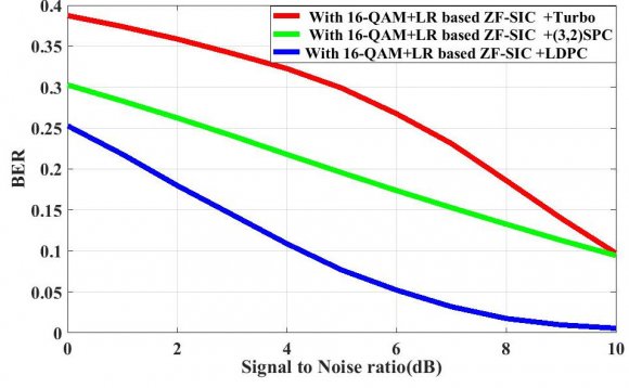
In this section, simulation results using MATLAB R2017 are presented to illustrate the significant impact of various types of signal detection and channel coding techniques on performance evaluation of a single-user digitally precoded5G compatible mmWave massive MIMO FBMC system in terms of bit error rate (BER) on encrypted audio signal transmission. It has been assumed that the channel state information (CSI) of the geometrically estimated mmWave large MIMO fading channel is available at the receiver and the fading channel coefficients are constant during simulation. The proposed model is simulated to evaluate the system performance with considering the following parameters presented in the Table 2.
16. VII. Conclusions
In this paper, the performance of single-user digitally precoded mmWave massive MIMO FBMC wireless communication system has been investigated on encrypted audio signal transmission under utilization of various modern channel coding and signal detection techniques. From the simulation results, it can be concluded that the presently considered single-user digitally precoded mmWave massive MIMO FBMC wireless communication system shows satisfactory performance with lower order digital modulation under implementation of Lattice Reduction(LR) based ZF-SIC signal detection and LDPC Channel coding technique.
![Secured Audio Signal Transmission in 5G Compatible mmWave Massive MIMO FBMC System with Implementation of Audio-to-Image Transformation Aided Encryption SchemeTable 1: Complex LLL Alogorithm (Using MATLAB Notation) f) Q-Less QR Decomposition Scheme With Q-less QR Decomposition scheme, the detected signal x ~ can be found based on the least squares approximate solution to are the channel matrix and received signal respectively. From H ~ channel matrix, an upper triangular matrix R ~ of the same dimension as H ~ is estimated and using the following steps, the detected desired signal x ~is computed[19] .](https://computerresearch.org/index.php/computer/article/download/1669/version/101221/2-Secured-Audio-Signal-Transmission_html/21885/image-2.png)

![Audio Signal Transmission in 5G Compatible mmWave Massive MIMO FBMC System with Implementation of Audio-to-Image Transformation Aided Encryption Scheme number of memory elements of each RSC encoder is 3.The turbo encoded binarydata arewhere such mathematical manipulation can be performed with a generator matrix G 1 . G 1 is found from H 1 with Gaussian elimination which can be written as follows: is found for message word x as follows c =xG 1 =[x :xP].](https://computerresearch.org/index.php/computer/article/download/1669/version/101221/2-Secured-Audio-Signal-Transmission_html/21889/image-6.png)
![Figure 1: Graphical representation of a (8, 4) LDPC code i) (3, 2) SPC Channel CodingIn SPC channel coding, the transmitted binary bits are rearranged into very small code words consisting of merely two consecutive bits. In such coding, (3, 2) SPC code is used with addition of a single parity bit to the message u = [u0, u1] so that the elements of the resulting code word x = [x0, x1, x2] are given by x0 = u0, x1 = u1 and x2 = u0 ?u1[22]. where, ? denotes the sum over GF(2)](https://computerresearch.org/index.php/computer/article/download/1669/version/101221/2-Secured-Audio-Signal-Transmission_html/21890/image-7.png)
| (2) | ||
| (3) | ||
| Year 2 018 | Year 2 018 | |
| 15 | ||
| ( ) E | b) Digital Precoding | ( ) E |
| © 2018 Global Journals 1 | © 2018 Global Journals |
| Data Type | Audio Signal |
| No of samples | 30,000 |
| Sampling frequency of audio signal | 48KHz |
| Carrier frequency | 28GHz |
| Encryption technique | Audio to image( size: 100×100×3 pixels) |
| Path loss constant | 3 |
| Path loss, dB for carrier frequency wavelength ? and transmitter-receiver distance , d | -20log 10 (?/4?d) |
| No of iteration used in LDPC decoding | 10 |
| Antenna configuration | 32 x 256 Large MIMO Channel |
| Channel Coding | LDPC, Turbo and (3,2)SPC |
| LDPC Channel decoding | Log-domain sum product |
| Digital Modulation | 16-QAM |
| Signal Detection Scheme | LR based linear detection, LR based ZF-SIC, CLLL based LR and Q-Less QR |
| SNR | 0 to 10 dB |
| Channel | AWGN and Rayleigh |